


Seams
There are six types of seams illustrated below.![]() Seams | Print Version
Seams | Print Version
Figure 1: Heat-bonded calibration hose seam.
![]()
Figure 2: Sewn calibration hose seam.
![]()
Figure 3: Heat-bonded liner-coated seam.

Figure 4: Heat-bonded inner liner seam.
![]()
Figure 5: Sewn liner-coated seam.

Figure 6: Sewn liner inner seam.

Installation Issues
Impregnation Issues
![]() Impregnation Issues | Print Version
Impregnation Issues | Print Version
Causes: During impregnation the layers of felt can slide over each other while passing through the nip rollers. The main force causing the inner layer(s) to pass through the nip rollers is the friction between the inner and outer layers.
Applying too much force by impregnating too quickly will overcome that friction causing the inner to move along inside the outer coated layer and bunch up.
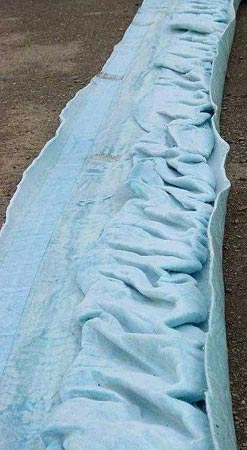
In the extreme examples below (Figures 1 and 2), the inner layer has gathered up as the liner was being impregnated.
The tighter the nip roller and the faster the wet out proceeds, the more likely it is that this bunching problem will occur.
Bunching of this sort can result in circumferential fins and undulations.

Inversion Issues
Stopped Inversions
![]() Stopped Inversions | Print Version
Stopped Inversions | Print Version
Causes: Inverting liners can stop inverting for a number of reasons. In any case, small diameter linings are more difficult to invert. Bends and other restrictions in the pipe may make inversion more likely to slow or stop.
It has been known, especially in larger, longer liners, for the resin to gel prematurely which, when reporting to the inversion face, causes the inversion to stop. This is the cause of the issue in Figure 1 below.
The seam area in particular has prematurely gelled which explains the straight piece of liner which protrudes from the inversion face. The felt has become embrittled by the area of hardened resin and, unable to sustain the temporary loads, has torn.
In Figure 2, the liquid resin is emerging from the inversion mouth. There appears to be a split in the inner layer on the lower right of the face.


Circumferential Fins
![]() Circumferential Fins | Print Version
Circumferential Fins | Print Version
Circumferential fins have been observed on finished linings. They are raised localized ridges which appear to involve only the coated layer, but the underlying felt may also be involved in some circumstances.
Causes: Circumferential fins may involve only the coated layer, but the underlying plain layer(s) may also be involved. The Figures below show circumferential fins of varying severity and in differing situations.
Fins are associated with an inequality in length of the coated layer and plain layers. This can be brought about during impregnation by inner layers of plain felt being forced to move intermittently relative to the coated layer.
An interesting example of how relative movement of layers has occurred is shown in the impregnation issues section.
At the inversion end, or when liners are inverted through changes of section, circumferential fins can arise due to the inverting liner dragging the previously inverted liner thus inducing fins. This can also occur due to the problem of air accumulating within the liner at the top of the water column during inversion allowing inner layers to slip relative to the inflated coated layer.


Longitudinal Fins
![]() Longitudinal Fins | Print Version
Longitudinal Fins | Print Version
Fins have been observed on finished linings. They are raised localized ridges which appear to involve only the coated layer, but the underlying felt may also be involved in some circumstances.
Causes: Reasons for the formation of longitudinal fins on the internal surfaces of liners. The occurrence of longitudinal fins may be associated with the difficulties of measuring the perimeter of the host pipe resulting in an oversized liner.
This is most likely to occur in irregular shaped pipes, for example in egg-shapes, flat topped or flat bottomed conduits. Another reason may be the unintentional relative movement of coated and underlying layers which can occur at any stage of manufacture, impregnation or installation. Once a local excess of coated material has been induced it is unlikely that it can be pulled out and will remain as a fin. A common location for a longitudinal fin is along the edge of the layflat, often at 90 degrees from seam. (See Figures 1 – 3 below).


Seams and Patch Repair Issues
Stained Seams
Stained seams have been observed on finished linings. They range from small dark spots in the seam center to dark patches which appear to emanate from seams.
Causes: Seams become stained due to water passing through the liner either during cure (hot water passing out) or after cure (groundwater passing into the liner). When hot water passes out, spots or stains are sometimes caused by impurities being filtered out of the water. Also, if water can find its way under the seam tape, it may track along the seam causing impurities to be filtered out in the seam area for some distance.
If seams become damaged during installation it would then allow water to pass out during cure and back in from the ground following the draining of the curing water.
It is also possible for resin to find its way directly underneath the seam tape and under certain conditions, to cure in such a way which causes small holes in the covering tape to melt along the edge of the white tape.
If the liner is porous due to poor impregnation or monomer boil then at a later date the water may be able to find a path from the groundwater to the inside surface of the liner depositing oxidized iron/manganese salts on the the surface of the coating.


Leaking Seams
Leaks have been observed on finished liners. They range from small drips to water pouring or jetting in.
Causes: Reasons for the formation of leaks on seams are associated with the initial formation of a hole in the seam brought about at some stage during installation.
Prior to this, any holes would have been apparent during impregnation. Once water/air/steam during cure has a route out through the liner, groundwater can then follow the same route producing the features in the Figures below.
A stress raiser at the edge of the seam tape may induce a split under excessive load.


Leaking Patch Repair
![]() Leaking patch Repairs | Print Version
Leaking patch Repairs | Print Version
Patch repairs carried out on liners either before or after installation have resulted in leaks and unsightly results. Patch repairs carried out before installation are repairs to the vacuum holes and resin addition holes.
Causes: Consequences of poor patch repairs are unsightly leaks and stains which detract from an otherwise good liner. Making a good patch repair is made more difficult when the air is warm and humid and the liner is cold enough to cause condensation that makes obtaining a dry surface hard to achieve.


Coating and Related Issues
Inward Folding of the Liner-Lifts
![]() Inward Folding of the Liner – Lifts | Print Version
Inward Folding of the Liner – Lifts | Print Version
Inward folding has been observed on finished liners, sometimes on the invert, but not exclusively. Such folds can be small, raised areas which do not seriously hamper flow or access. Equally, they can be catastrophic, almost completely obstructing flow and access.
Causes: The formation of lifts as opposed to fins is associated with the reduction or removal of internal pressure within a liner.
While a cured liner is hot, it has a reduced stiffness. If the internal pressure is removed while the liner is still hot then external water pressure may overcome the buckling resistance of the liner.
Even if the internal pressure is not removed, it is possible for side connections to fill with water to such a level that it overcomes the internal pressure in the liner.
In the case of a liner which has been damaged, water may find its way under the coating and wash some of the resin out before it has cured. Depending on the external water pressure on the removal of the internal pressure the liner, and with the liner being partly devoid of resin, it may collapse in those locations.
In some cases, the water circulation may have been inadequate such that the top of the liner has cured, but the bottom has not. In this case, it is possible for the invert to lift under the influence of external ground water pressure after internal pressure is removed.


Damage to the Surface of Liner
![]() Damage to Liner Surface | Print Version
Damage to Liner Surface | Print Version
Damage to the liner surface, including cuts to the surface, seams, and cracks, have been observed on finished liners.
Causes: Damage can occur to liners at any stage after vacuum impregnation. Damage to a liner before impregnation would be revealed due to the loss of vacuum.
After impregnation, the liner passes through and over rollers including the impregnation nip rollers. Any rollers which are contaminated with catalyzed resin from a previous job could leave hard projections of cured resin on the rollers which are capable of damaging the coating. Similarly, any uneven or rough surfaces, including boots, that have significant contact with the liner could also damage the coating.
If the components used in association with liner end detail, hold-back rope, or hose attachment, during inversion are inadequately taped the coating could be damaged especially if the inversion head is too low and the liner is allowed to run with the inverted liner not up to size.
Care should be taken to keep the liner away from roller end fittings and to enter it centrally through the inversion ring. The latter reduces the drag on the top ring. Drag on the top ring, especially with large diameter liners, can drag the cuffed-back liner at least partly off the top ring which could potentially cause damage from the BandIt buckles.


Significance of Atypical Features
![]() Signficance of Atypical Features | Print Version
Signficance of Atypical Features | Print Version
Impregnation issues are associated with the bunching up of the inner liner(s) and are unacceptable.
Inversion issues
- Stopped inversions due to premature cure are clearly catastrophic failures.
- Circumferential fins, unless slight, are unacceptable due to the possibility of deposition upstream. Because they are associated with the thickening of the pipe wall, such fins can be ground-off.
- Longitudinal fins, even moderate in nature, are not detrimental to the structural or hydraulic performance of the liner.
Seams and patch repair issues
- Stained seams are often due to water passing through in small quantities and impurities filtering out. Unless significant resin loss has resulted, stained seams are a question of aesthetics.
- Leaking seams are unacceptable. It is important that the liner is impregnated under adequate vacuum and at the correct nip roller gap. This will normally, with conventional catalyst cocktails, ensure a low porosity and result in sound seams. If the leaks are not too extensive, then a grout packer may be used to correct this issue.
- Leaking patch repairs through which groundwater can leak are unacceptable. It is possible that after grinding away the patch, a grout packer may be used to correct this issue.
Coating-related issues
- Bubbles on liners can be removed if they are unacceptable aesthetically. If they are caused by ingress of groundwater then some means may be needed to prevent further ingress.
- Spots and other Stains (e.g., on seams) are associated with leaks of water through small holes in the coating. The cause of the holes is discussed in the spots section.
- Uneven finishes on liners are typified by surface irregularities and although appear unsightly when viewed along the pipe on CCTV, do not detract from the structural or hydraulic performance of the liner. Air pockets behind liners are only of significance under high external head.
Inward folding of the lining are a potentially serious problem, but can in favorable circumstances be overcome by inverting a dry liner through the problem liner and circulating hot water. This should soften the liner sufficiently so that it can be reshaped. Do not apply a high head until hot or the liner may crack.
Damage to the surface of liners can be caused by a range of factors. The coating can be ripped and gouged by sharp objects used for rope end/soft end fittings. Alternatively, damage can be caused to the coating by dragging the liner over rough surfaces. In any case, if such damage results in water leaks, then it is unacceptable and should be repaired.
Liner Design Considerations
![]() Liner Design Considerations | Print Version
Liner Design Considerations | Print Version
To access photographs, video clips, causes and solutions that address liner design issues, select the appropriate link.
Cured in place pipeliners, in the normal case of underground sewers, are designed to withstand hydrostatic loading due to external groundwater pressure. In addition, some liners may be designed to resist the effects of soil loading and loads superimposed on the soil loads (e.g., traffic loads).
Except in significantly out-of-round pipes (e.g., ovoid pipes) the failure mode of pipeliners is considered to be due to buckling. Further, pipeliners are designed to transmit flow in the pipe as efficiently as possible, taking into consideration the relative smoothness of the walls and loss of cross-sectional area. Pipeliners are designed to significantly reduce infiltration and exfiltration to and from the surrounding soil.
Impregnation issues are associated with the bunching up of the inner liner(s) and are unacceptable.
Inversion issues
- Circumferential fins, unless slight, are unacceptable due to the possibility of deposition upstream. Because they are associated with the thickening of the pipe wall, such fins can be ground-off.
- Longitudinal fins, even moderate in nature, are not detrimental to the structural or hydraulic performance of the liner.
- Seams and patch repair issues An aspect of atypical features associated with seams and patch repairs is related to leaks. Where significant resin loss has occurred then structurally, an incomplete ring of pipe exists at that point.
- Stained seams are often due to water passing through in small quantities and impurities filtering out. Unless significant resin loss has resulted, stained seams are a question of aesthetics.
- Leaking seams are unacceptable. It is important that the liner is impregnated under adequate vacuum and at the correct nip roller gap. This will normally, with conventional catalyst cocktails, ensure a low porosity and result in sound seams. If the leaks are not too extensive, then a grout packer may be used to correct this issue.
- Leaking patch repairs through which groundwater can leak are unacceptable. It is possible that after grinding away the patch, a grout packer may be used to correct this issue.
Coating-related issuesAn aspect of atypical features associated with coating-related problems is that of minor distortion of surfaces. This aspect is of no consequence either hydraulically or structurally.
- Bubbles on liners can be removed if they are unacceptable aesthetically. If they are caused by ingress of groundwater then some means may be needed to prevent further ingress.
- Uneven finishes on liners are typified by surface irregularities and although appear unsightly when viewed along the pipe on CCTV, do not detract from the structural or hydraulic performance of the liner. Air pockets behind liners are only of significance under high external head.
Inward folding of the lining An aspect of atypical features associated with inward folding of liners is a dramatic loss of cross sectional area. Not only is this of significance hydraulically, but also because the circular cross-section with close tolerance to the existing pipe wall required for buckling resistance is lost. This is potentially a serious problem, but can in favorable circumstances be overcome by inverting a dry liner through the problem liner and circulating hot water. This should soften the liner sufficiently so that it can be reshaped. Do not apply a high head until hot or the liner may crack. As a last resort, the lift section may need to be cut out completely and a new length of liner installed.
- Spots and other Stains (e.g., on seams) are associated with leaks of water through small holes in the coating. This problem is included here because it can lead to resin loss over an extended area and subsequent low strength followed by distortion, even lifting, of the liner. The cause of the holes is discussed in the spots section.
Damage to the surface of liners can be caused by a range of factors. The coating can be ripped and gouged by sharp objects used for rope end/soft end fittings. Alternatively, damage can be caused to the coating by dragging the liner over rough surfaces. In any case, if such damage results in water leaks, then it is unacceptable and should be repaired.
